Almost finished! While prototyping, I swapped out the liquid reward delivery system (a solenoid gating the flow between a lick spout and a reservoir) for a test LED that ran at the same voltage. But, as any student of electronics knows, voltage is not the only thing that matters.
In the final testing stage, I replaced the LED with the real part. Now, I got very erratic Arduino behavior while deploying the solenoid (eg to prime the liquid delivery tubing and make sure the liquid was continuous without air bubbles).
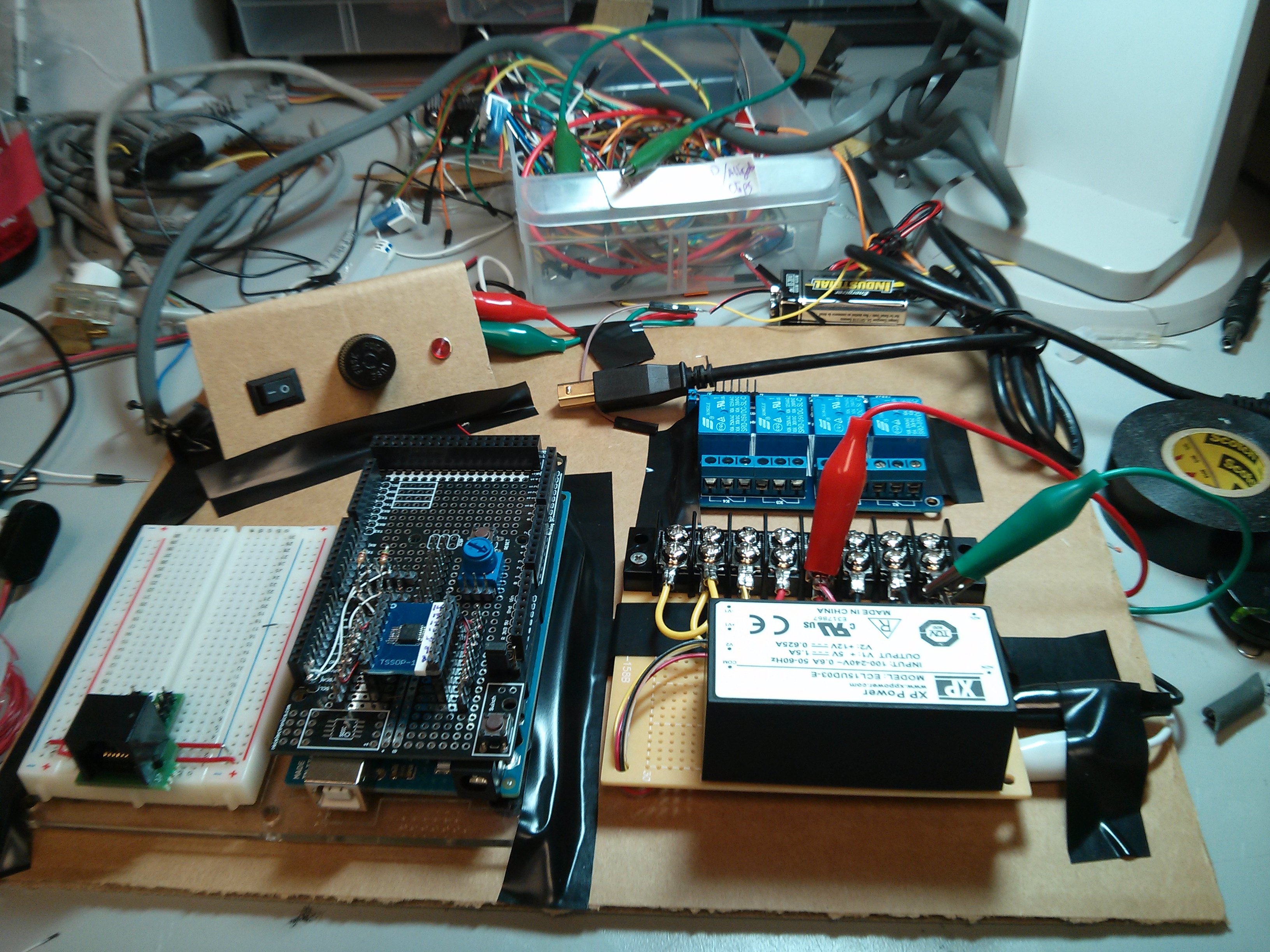
At first, I thought my power supply was not sufficient to run both the Arduino and the solenoid at the same time (they are both drawing from the same 12V, 625mA supply). However, swapping for another wall wart or running the Arduino from the USB connection resulted in the same issues (of course, the grounds were always tied together). Besides that, the solenoid I’m using is only rated for 1 watt, translating to a measly 83mA at 12V. After some googling, it turns out that sudden power demands may spike or drop the voltage, and so one potential answer is to add a capacitor to minimize that disruption in power. Because I’m only using one solenoid, I tried inserting a 220uF capacitor between the positive and negative leads of the solenoid (had I many other such components, it might make more sense to put the capacitor closer to the power supply).
Capacitor in place, no more erratic behavior! The capacitor acts as an extra reserve of charge, so when the solenoid is activated, it uses both the stored charge and the power supply, resulting in no (or at least less) voltage drop.
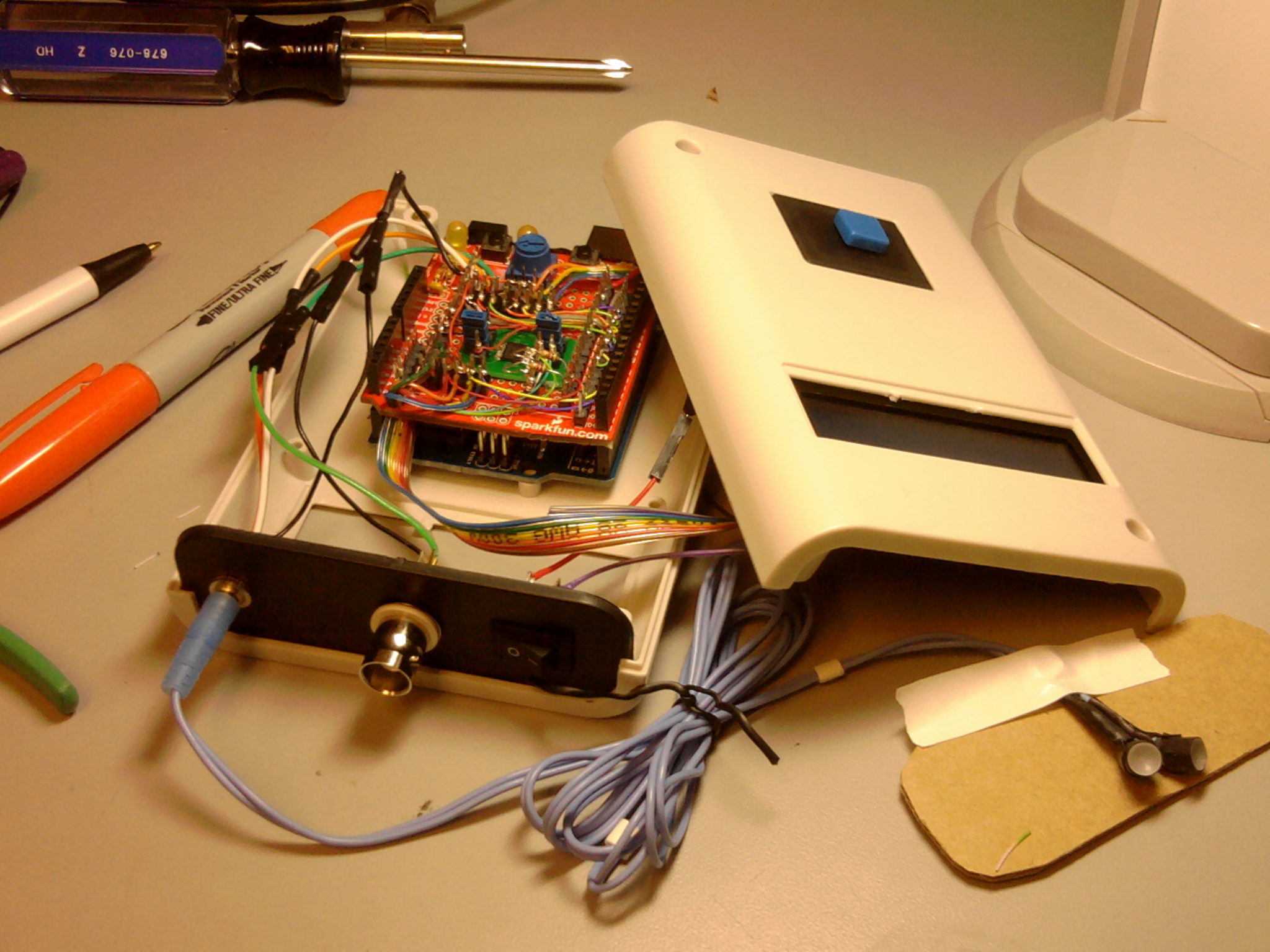
Round two of the Arduino-based experimental control unit! In addition to the features of the original unit (visual stimuli, TTL trigger to begin trial, etc), this version will monitor animal behavior with a lickometer (i.e., detect when the animal licks on a spout) and deliver liquid reward when some requirement is fulfilled. For example, in order to receive a reward, the animal waits for a visual cue and then licks four times within a one second window.
Like the first unit, this version will be used in conjunction with 2-photon imaging to visualize large ensemble neural activity in awake animals. With the addition of behavioral input, we will be able to see how behavioral conditioning changes activity in the brain.
So far, I’ve tested each component and made sure the power supply provides enough juice. Here is the initial layout of the circuit that I will eventually cram into a plastic housing:
In order to implement a pause pushbutton, I used the ThreadKit library to create threads that run in parallel. At startup, a thread to listen for the button state is automatically initiated. The unit begins in the “paused” state and prompts the user to begin the experiment by pressing the button. At button press, the button state thread triggers an event that will lead to the trial routine (TTL pulse, delay, and LED stimulus presentation). Any time the user presses the pause button, the current trial will finish executing and then the state will switch back to “paused” until a second button press.
One of the key features of this unit is that the brightness of the LED stimuli can be set in code. While a radial potentiometer outputs variable resistance depending on the slider position, a digital potentiometer has a fixed series of resistors that are logically gated, so by commanding the digital pot, a particular series can be connected to produce the desired resistance. I chose Microchip’s MCP4651 because it uses I2C communication, has two separate wipers (thus, each of the two LEDs could have different brightness), and produces an appropriate range of resistance for the LEDs we use (SunLED XZDG55W).
In addition to the Wire reference, I found this page to be extremely helpful in figuring out how to get Arduino I2C communication working with the selected digital pot. Of particular use is this little routine that cycles through all possible byte commands to find those that successfully communicate with the digital pot. This was very helpful to me as I slogged through the datasheet trying to figure out exactly how to “talk” to the digital pot.
/* Goggle Stimulator v1
by Emma Roach, May 2013
Further documentation: https://emmaberylroach.wordpress.com/category/devices/mouse-goggles/

Features:
* TTL pulse indicates impending stimulus onset
* LED stimuli of varying brightness (controlled via I2C with Microchip digital potentiometer MCP4651)
* user-defined stimulus parameters include LED brightness/duration and intervals between events
* LCD screen displays current state of experiment
* Push button allows experiment to be paused/unpaused (note that the current trial will execute before the pause)

Typical trial control (repeated in an infinite loop or up to [max_trials]):
* TTL pulse of length [TTL_duration]
* wait length of [trigger_delay]
* goggles turned on
* wait length of [goggle_duration]
* goggles turned off
* wait length of [minITI] + random length between 0 and [rand_delay]

This code uses the Threadkit library for cooperative multi-threading
* For more information: https://code.google.com/p/threadkit/

PLEASE NOTE:
* The unit should be powered off when not in use.
* Once the unit is powered back on, pressing the push button begins the trial presentation loop.
* During power up, the goggles will glow briefly and then shut off. To avoid presenting unintended
stimuli, either power on the unit prior to placing the goggles or unplug the goggles from the
unit until just before starting the experiment.
*/

// Libraries to include
#include <Arduino.h>
#include "ThreadKit.h"
#include <Wire.h>
#include <LiquidCrystal.h>

//*****************************************************
// The following block contains user-defined variables.
// All temporal values are expressed in milliseconds.

int minITI = 2000; //minimum time between trials, ie inter-trial interval (ITI)
int rand_delay = 0; //upper boundary of random addition to ITI
int trigger_delay = 100; //interval between TTL pulse and goggle onset
int ttl_duration = 100; //duration of TTL pulse
int goggle_duration = 200; //duration of goggle stimulus
int max_trials = 10; //total number of trials to present (set to 0 for infinite)
byte goggle1R = 240; //goggle 1 resistance, range 0-255, linear scale where 255 = brightest
byte goggle2R = 240; //goggle 2 resistance

// If you change anything beyond this point you
// run the risk of breaking the code's functionality!
//******************************************************

// Initialize the LCD library with the numbers of the Arduino interface pins
LiquidCrystal lcd(7,8,9,10,11,12);

// Wire transmission variables to command digital potentiometer (I2C protocol)
byte slave = 0; //address to begin general transmission with potentiometer
byte goggle1 = 128; //command byte: write next byte to wiper 0
byte goggle2 = 144; //command byte: write next byte to wiper 1
byte off = 0; //wiper value for maximum resistance

// Designate Arduino pins for button input and TTL output
int button = 5; //pin for button press input
int ttl = 6; //pin for TTL output

// Miscellaneous state parameters
static boolean paused = 1; //state of experiment
static int trials = 1; //total number of trials presented

// EVENTS
// When broadcasted, events trigger the initiation of individual threads.
// The event "STARTUP" is broadcast by default when the unit is powered on.

EVENTS (
        TRIAL_START,
        GO
       );

// User_setup: equivalent to the typical Arduino "setup" function.
// Executes before any of the threads begin.
void user_setup ()
{
    //make dummy connection (the first command fails without this)
    Wire.beginTransmission(slave);
    Wire.endTransmission();

    //Command max resistance for each LED
    Wire.beginTransmission(slave);
    Wire.write(goggle1); //write next byte to wiper 0
    Wire.write(off);
    Wire.write(0);
    Wire.endTransmission();

    Wire.beginTransmission(slave);
    Wire.write(goggle2); //write next byte to wiper 1
    Wire.write(off);
    Wire.write(0);
    Wire.endTransmission();

    //Initialize LCD and print starting message
    lcd.begin(16, 2);
    lcd.setCursor(0,1);
    lcd.print("press to begin");

    //Configure the button and TTL pins for input and output
    pinMode(button,INPUT);
    pinMode(ttl,OUTPUT);

    //Seed the random number generator with floating (highly variable) analog input
    //(comment out if the same "random" ITI sequence is desired across experiments)
    randomSeed(analogRead(0));
}

// THREADS
//Each thread is initiated via an event broadcast: BEGIN_THREAD (EVENT)
//Once initiated, the thread will run in parallel with other existing threads
//
//* note: top-level variables shared between threads must be declared "static"
//(e.g. the state parameters [trials] and [paused])

//This thread listens for button input and triggers trial presentation when unpaused
THREAD (button_wait)
{
    BEGIN_THREAD (STARTUP); //automatically initiated at powerup

    while (true) {

        WAIT (digitalRead(button)); //wait until user button has been pushed

        if (paused) { //this button press indicates an "un-pause"
            paused = 0;
            broadcast (GO); //initiate main_th thread
        }
        else { //this button press indicates a "pause"
            paused = 1;
        }

        WAIT (!digitalRead(button)); //make sure button has been released before continuing to monitor button state

    }

    END_THREAD;
}

//This thread is triggered when the experiment is "un-paused"
THREAD (main_th)
{
    BEGIN_THREAD (GO);

    lcd.setCursor(0,0);
    lcd.print("trial #");

    while (!paused){

        //check if max number of trials have been presented
        if ((max_trials > 0) & (trials > max_trials)) {
            lcd.setCursor(0,1);
            lcd.print("exp. completed ");
        }
        else {
            lcd.setCursor(0,1);
            lcd.print("exp. running ");
            WAIT_DELAY (minITI + random(rand_delay)); //wait minimum ITI plus random delay
            broadcast (TRIAL_START); //initiate trial thread
        }
    }

    lcd.setCursor(0,1);
    lcd.print("exp. paused ");

    END_THREAD;
}

THREAD (trial)
{
    BEGIN_THREAD (TRIAL_START);

    lcd.setCursor(7,0);
    lcd.print(trials);
    lcd.setCursor(13,0);

    //execute TTL pulse
    digitalWrite(ttl,HIGH);
    lcd.print("TTL");
    WAIT_DELAY(ttl_duration);
    digitalWrite(ttl,LOW);
    lcd.setCursor(13,0);
    lcd.print(" ");

    //delay between TTL and goggle onset
    WAIT_DELAY(trigger_delay);

    //turn on goggles
    Wire.beginTransmission(slave);
    Wire.write(goggle1); //write next byte to wiper 0
    Wire.write(goggle1R);
    Wire.write(0);
    Wire.endTransmission();

    Wire.beginTransmission(slave);
    Wire.write(goggle2); //write next byte to wiper 0
    Wire.write(goggle2R);
    Wire.write(0);
    Wire.endTransmission();

    //wait stimulus duration
    WAIT_DELAY (goggle_duration);

    //turn off goggles
    Wire.beginTransmission(slave);
    Wire.write(goggle1); //write next byte to wiper 0
    Wire.write(off);
    Wire.write(0);
    Wire.endTransmission();

    Wire.beginTransmission(slave);
    Wire.write(goggle2); //write next byte to wiper 0
    Wire.write(off);
    Wire.write(0);
    Wire.endTransmission();

    //increment trial count
    trials++;

    END_THREAD;
}

//list of all threads
THREADS (
        button_wait,
        main_th,
        trial
        );
I designed an Arduino-based stimulus device to present visual cues to a mouse undergoing an imaging experiment. The unit features the following:
1) TTL output to trigger image acquisition at trial start
2) user push button to pause experiment
3) stimulus brightness adjustable in code via digital potentiometer
4) LCD displays status of experiment
Next up: code including I2C control of digital pot.